CNC transformation of XB4450 milling machine (Figure)

1. Reason for transformation

    The XB4450 milling machine is a copy milling machine produced by Kunming Machine Tool Plant. The basic parameters are: maximum milling length 900mm, maximum milling width 500mm, maximum milling height 350mm. Due to long working hours, the milling machine is aging, the mechanical transmission deviation is large, resulting in low precision and slow speed; single-axis control, complicated circuit, cumbersome operation, unstable performance, and low efficiency. In order to adapt to the development of modern manufacturing industry and rational use of resources, the following transformations were carried out.

2. Electrical part transformation

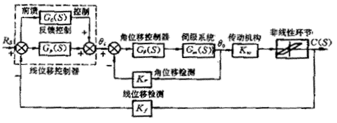
The modified CNC system consists of two inner and outer position loops. The internal closed loop is a closed loop position of the corner position, the detecting component is an optical encoder disk mounted on the motor shaft, and the driving device is an AC servo motor (instead of the original thyristor controlled DC motor), thereby constituting an input q i , the output The following system is q 0 . Due to the higher resolution of the encoder, the feedback uses digital pulse servo, and some uses double pulse input control, so the anti-interference ability is strong. The performance of the inner ring is stable. Compared with the open-loop control before the modification, the rotation accuracy is obviously improved. The external position loop adopts a grating with a resolution of 0.05 μm as a line displacement detecting component to directly obtain the displacement information of the machine tool table in the machining. The digital pulse is transmitted to the computer to form a full-closed control, which ensures the positioning accuracy of the machine. The driving device is driven by the driving device of the inner ring angle follower system, and the displacement accuracy of the table is determined by the line displacement detecting element. The double closed loop control not only has the position control precision of the full closed loop system, but also has the precision stability of the full closed loop control, which effectively ensures the response speed and machining accuracy of the machine tool.

    1
    figure 1

(1) Stability analysis

Since the internal corner closed loop does not contain the gap nonlinear link, by properly designing the local linear system, it can be made into a fast follower system without overshoot, and its dynamic characteristics can be approximated as

q 0 (S) / q i (S)=K q /(T q S+1)

Where: K q —— corner closed loop gain

  1. T q ——turn ring closed time constant
    Although the outer loop of the system contains nonlinear links, the controller is designed to

    G p (S)=K p /S
    In the formula K p - integral link time constant
    Correcting the system to type I and selecting the system gain reasonably avoids the intersection of the frequency characteristic curve of the system and the negative inverse curve of the nonlinear link or encloses it, thus ensuring stable operation of the system. Obviously, when T q is small, q 0 (S) / q i (S) = K 0 , the system will have stronger stability.

(2) Following error analysis

The above scheme can ensure the stable operation of the system, so the influence of the nonlinear factor can be neglected and the transfer function of the system can be obtained.

1

  1. The system design makes the feedback coefficient K f =1, feedforward channel

    1

The above equation shows that the double closed loop system has ideal dynamic performance and following accuracy.

The Mitsubishi PLC is used to process complex circuit logic relationships, which makes the circuit simplified, stable in performance and easy to maintain. In addition, in order to make the machine tool meet the requirements of processing different materials, the spindle uses the frequency converter to perform stepless speed regulation to ensure that the torque change is small when the spindle speed changes.

3. Mechanical part transformation

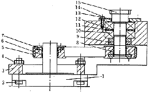
First of all, the gearboxes of the X, Y, and Z three-direction carriages are removed, and the motor directly drives the ball screws through the pulleys and the timing belts, thereby driving the carriages to move. Therefore, the mechanical structure is simpler and the transmission error is reduced. The structure in the Z direction is taken as an example to illustrate its new structure. The Z-axis motor is mounted below the machine according to customer requirements. The connection method is shown in Figure 2.
The pulley 7 is fixed on the motor shaft through the tension sleeve, and the pulley 8 is driven by the belt. The pulley 8 is fixed by the tension sleeve and the ball screw (the ball screw is fixed at one end and fixed at one end), and drives the Z. Move to and from the board. Among them, the tensioning sleeve mechanism is a new type of keyless connection method developed in recent years. It is easier to ensure accuracy and easier to install than the keyed connection, and its structure and size have been standardized.

1


1. Motor 2, 13. Screw 3. Support seat 4, 9. Nut 5. Timing belt 6, 8 tension sleeve
7. Synchronous gear 10. Bearing 11. Outer spacer 12. Inner spacer 14. Compression flange 15. Ball screw
figure 2

4. Transformation results

According to the customer's reflection, the milling machine after the transformation has stable performance and high processing precision. The machine adopts three-axis linkage, which can automatically process for more complex mold surfaces and shaped workpieces, and has fast calculation speed, good positioning accuracy and high price performance ratio, which is suitable for the needs of modern manufacturing.

KMP Cat Parts

KMP Cat Parts,Cat Engine Parts,KMP Cat Stamping Parts,Custom KMP Cat Parts,CAT Spare Parts

JINING SHANTE SONGZHENG CONSTRUCTION MACHINERY CO.LTD , https://www.stszcmparts.com